Technical Differences, Application Standards and How to Choose the Right Medium Voltage Connector
In medium voltage cable systems, separable connectors are widely used for safe cable termination and plug-in connections on transformers, switchgear, RMU and underground distribution networks. However, many buyers, engineers and EPC contractors still ask an important question:
What is the difference between IEEE 386 separable connectors and IEC separable connectors?
Although both systems are designed for medium voltage cable accessories, they differ significantly in design philosophy, interface dimensions, electrical ratings, test methods and target markets.
This technical guide explains the real engineering differences between IEEE 386 connectors and IEC separable connectors, helping utilities, OEM manufacturers and project buyers select the correct product.

What Is a Separable Connector?
A separable connector is a fully insulated and shielded plug-in cable accessory used to connect medium voltage cables to energized equipment such as:
- Pad mounted transformers
- Ring Main Units (RMU)
- Medium voltage switchgear
- Cable branch cabinets
- Compact substations
- Renewable energy distribution systems
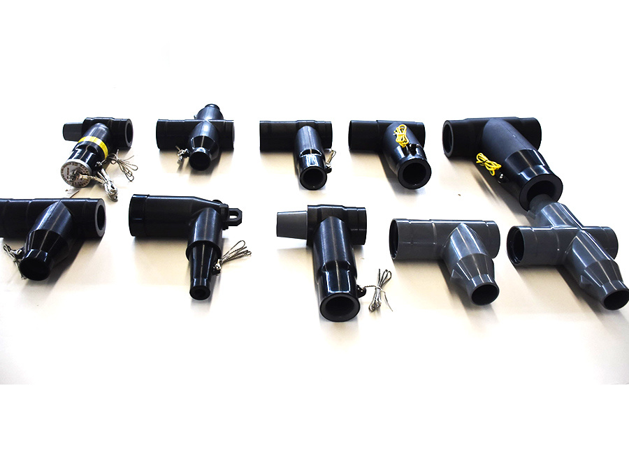
Common types include:
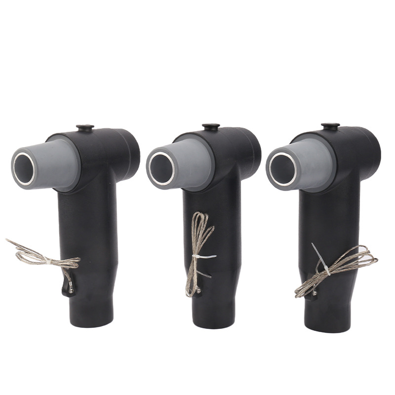
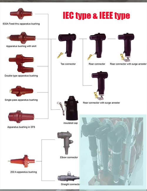
- Elbow type separable connector
- Straight connector
- Tee connector
- Deadbreak connector
- Load break elbow connector
These connectors provide safe, compact and maintainable cable termination without exposed live parts.
What Is IEEE 386?
IEEE 386 is a North American standard titled:
Separable Insulated Connector Systems for Power Distribution Systems Above 600V
It is widely used in:
- United States
- Canada
- Latin America
- Utility systems based on ANSI / IEEE equipment standards
IEEE 386 defines requirements for:
- Interface dimensions
- Interchangeability
- Current ratings
- Load break performance
- Fault closing capability
- Shielding performance
- Electrical testing
The most common IEEE connector types are:
- 15kV 200A load break elbow connector
- 25kV elbow connector
- 35kV separable connector
- 600A deadbreak T-body connector
What Is IEC Separable Connector Standard?
IEC style separable connectors are commonly designed according to:
- IEC 60502-4
- EN 50180
- EN 50181
- HD 629 series
They are widely used in:
- Europe
- Middle East
- Africa
- Asia
- International utility projects using IEC switchgear
IEC connectors are common on:
- Ring Main Units
- GIS switchgear
- Dry type transformers
- Oil immersed transformers
- Compact substations
Typical interface sizes include:
- Interface A
- Interface B
- Interface C
- Interface D
- Interface E
- 250A / 400A / 630A / 1250A systems
Core Technical Difference: IEEE vs IEC Philosophy
The biggest difference is not voltage level. It is system architecture and interface philosophy.
IEEE 386 Focuses on Utility Distribution Simplicity
IEEE connectors were developed heavily around North American underground utility networks, especially:
- Pad mounted transformers
- Radial and loop feed systems
- 200A load break switching
- Field replaceable elbows
This is why load break elbow connectors are highly common in IEEE systems.
IEC Focuses on Modular Equipment Interfaces
IEC systems developed around compact switchgear and multi-manufacturer interchangeability. Therefore IEC connectors emphasize:
- Standardized bushing interfaces
- Compact dimensions
- High current plug-in systems
- RMU and switchgear integration
IEEE 386 vs IEC Separable Connector Comparison Table
| Item | IEEE 386 Connector | IEC Connector |
|---|---|---|
| Main Markets | USA, Canada | Europe, Asia, Middle East |
| Typical Equipment | Pad mounted transformer | RMU, GIS, Switchgear |
| Common Type | Elbow connector | Tee / Straight connector |
| Current Ratings | 200A / 600A | 250A / 400A / 630A / 1250A |
| Load Break Function | Very common | Depends on design |
| Interface Standard | IEEE geometry | EN 50180 / EN 50181 |
| Cable Network Style | Utility underground feeders | Compact urban networks |
| Interchangeability | IEEE compatible brands | IEC interface class based |
Mechanical Interface Differences
IEEE 386 Interface
IEEE systems commonly use:
- Bushing well
- Bushing insert
- Load break probe
- Parking stand accessories
A 200A elbow type separable connector can be hot-stick operated for switching under rated load.
IEC Interface
IEC systems usually use:
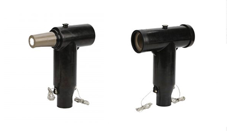
- Rear plug-in bushings
- Front plug-in bushings
- Standardized cone interfaces
- Bolted conductor studs
IEC systems are generally more compact for switchgear panel layouts.
Electrical Performance Differences
Load Break Capability
One of the biggest practical differences:
IEEE 200A Elbow Connector
Often designed for:
- Load make / load break operation
- Switching transformer feeders
- Sectionalizing cable loops
IEC Tee Connector
Usually intended as:
- Deadbreak connection
- Installed de-energized
- Disconnect after isolation
(Some IEC load break designs exist, but less universal.)
Insulation and Shielding Design
Both systems today commonly use:
- EPDM rubber
- Silicone rubber
- Molded stress control layer
- Conductive outer shield
- Capacitive test point (depending on design)
High quality connectors should also minimize:
- Air voids
- Interface gaps
- Partial discharge
- Moisture ingress
Triple-layer molding technology is commonly preferred for premium products.
How to Choose IEEE 386 or IEC Connector
Choose IEEE 386 If Your Project Uses:
- Pad mounted transformers
- North American utility equipment
- 200A load break elbow systems
- ANSI bushings
- Retrofit with Elastimold / Cooper / Hubbell style interfaces
Choose IEC Connector If Your Project Uses:
- RMU switchgear
- European transformer bushings
- 630A plug-in systems
- Compact substations
- EN / IEC specified tenders
Common Buying Mistake to Avoid
Many buyers only compare voltage level such as 15kV or 24kV.
That is not enough.
You must also confirm:
- Interface standard
- Current rating
- Cable conductor size
- Cable insulation diameter
- Load break or deadbreak requirement
- Bushing dimensions
- Installation environment
Wrong interface selection can make connectors impossible to install.
For OEM Buyers and EPC Contractors
Before ordering separable connectors, request:
- Interface drawings
- Type test reports
- Routine test reports
- Material data (EPDM / Silicone)
- Partial discharge test data
- Torque and installation guide
For replacement projects, send existing connector photos and dimensions.
Why Quality Matters in Separable Connectors
Poor quality medium voltage connectors can lead to:
- Partial discharge failure
- Tracking marks
- Moisture ingress
- Thermal runaway
- Interface flashover
- Costly outage events
For critical networks, always choose tested IEEE 386 connectors or certified IEC separable connectors from experienced manufacturers.
Final Conclusion
There is no universal winner between IEEE 386 vs IEC separable connector systems.
The correct choice depends on:
- Installed equipment standard
- Regional market requirements
- Load break switching needs
- Space constraints
- Utility specifications
If your system is based on North American transformer and feeder design, IEEE 386 elbow connectors are often the best solution.
If your network uses RMU, compact substations and EN-standard equipment, IEC tee or straight plug-in connectors are usually the better fit.
Need Help Selecting the Correct Connector?
If you are unsure whether your project requires IEEE 386 elbow type separable connector or IEC 630A tee connector, send us:
- Equipment nameplate
- Voltage class
- Bushing photos
- Cable size
- Project country
Our engineering team can recommend the correct medium voltage cable accessory quickly.