

High-Efficiency Cast Resin Dry-Type Transformers for Data Centers
Premium K-Factor Rated | 1000kVA – 3150kVA | Class H Insulation | IEEE / IEC Compliant
Engineered specifically for mission-critical data center power chains, our K-factor rated cast resin dry-type transformers deliver superior harmonic handling, low losses, and high thermal stability. Designed to feed UPS systems, PDU inputs, and non-linear IT loads, these transformers help reduce PUE while ensuring 24/7/365 reliability.
This landing page covers the data center optimized range (1000kVA – 3150kVA) . For other ratings, refer to our standard SCB10 series:
- SCB10 11kV Class (100kVA – 4000kVA) → View Product Page
- SCB10 33kV Class (50kVA – 2500kVA) → View Product Page
Why Data Centers Need K-Factor Rated Transformers
Modern data centers contain non-linear loads: UPS rectifiers, switch-mode power supplies, servers, and storage devices. These loads generate harmonic currents (especially 3rd, 5th, 7th, 9th orders) that cause:
| Problem | Consequence |
|---|---|
| Excessive winding eddy losses | Local overheating, reduced transformer life |
| Neutral conductor overloading | Fire risk, voltage distortion |
| Increased RMS current without useful power | Higher losses, lower efficiency, elevated PUE |
| Resonance with power factor correction capacitors | Equipment damage |
A K-factor rated transformer is designed with:
- Reduced flux density to accommodate harmonic flux
- Larger neutral bushing (200% of phase rating for K-13)
- Double-sized neutral conductor inside windings
- Enhanced winding eddy loss mitigation (transposed conductors, foil windings)
Our K-4, K-7, K-13, and K-20 rated transformers directly address these issues per IEEE C57.110.
Technical Overview – Data Center Optimized Range
| Parameter | Value / Range |
|---|---|
| Rated Power | 1000 kVA / 1250 kVA / 1600 kVA / 2000 kVA / 2500 kVA / 3150 kVA |
| Primary Voltage | 11 kV / 10.5 kV / 10 kV / 6 kV (customizable) |
| Secondary Voltage | 0.4 kV / 0.415 kV / 0.433 kV / 0.48 kV (480V for US data centers) |
| K-Factor Rating | K-4 / K-7 / K-13 / K-20 (specify based on harmonic survey) |
| Vector Group | Dyn11 (standard – recommended for UPS input) |
| Impedance Voltage | 6% or 8% (6% for better voltage regulation; 8% for higher fault current limiting) |
| Insulation Class | H (180°C) – Standard for data center thermal margin |
| Cooling | AN (air natural) / AF (air forced – increases kVA by ~33%) |
| Winding Material | Copper (standard) / Aluminum (optional) |
| Core Material | High-permeability grain-oriented silicon steel (MOH grade) |
| Standards | IEC 60076, IEEE C57.12.01, IEEE C57.110 (K-factor), NEMA TP-1 |
K-Factor Selection Guide for Data Centers
| Typical Data Center Load | Recommended K-Factor | Notes |
|---|---|---|
| Legacy servers + UPS with 6-pulse rectifier | K-13 | High harmonic content (30-40% THD) |
| Modern servers + UPS with 12-pulse or IGBT rectifier | K-7 | Moderate harmonics (15-25% THD) |
| Fully optimized with active harmonic filters | K-4 | Low harmonics (<10% THD) |
| Mixed loads, high density, future expansion | K-20 | Maximum margin for unknown harmonic growth |
Engineering recommendation: For new data centers without a harmonic study, specify K-13 as a conservative choice. For retrofit or upgrade projects, perform a harmonic survey first.
Key Engineering Features for Data Centers
1. Class H Insulation (180°C)
- 20°C higher thermal margin than standard Class F (used in SCB10 series)
- Allows for emergency overload without accelerated aging
- Ideal for N+1 redundant configurations where a single transformer may carry 100% load during maintenance
2. Low Losses for PUE Reduction
- No-load losses: ≤ 1800W for 2000kVA unit (optimized core)
- Load losses at 75°C: ≤ 17000W for 2000kVA unit (copper windings)
- Total losses 10-15% lower than standard dry types → reduces cooling load in electrical room
3. Superior Harmonic Handling
- Double-sized neutral bushing (standard for all K-factor units)
- Full-height copper foil windings on LV side – minimizes eddy losses
- Interleaved disc windings on HV side – reduces harmonic flux
4. Low Partial Discharge
- Vacuum cast resin process ensures PD < 10pC at 1.73 × rated voltage
- Critical for long-term reliability in 24/7 operation
5. Low Noise
- Optimized core step-lap joints → ≤ 62 dB(A) at 1m (for 2000kVA)
- Optional enclosure with acoustic damping available
Compliance & Testing
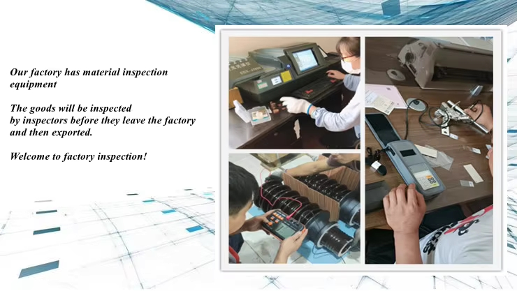
Each data center transformer is factory tested per IEEE C57.12.91 and IEC 60076-11. The Factory Acceptance Test (FAT) includes:
- Winding resistance measurement (all taps)
- Voltage ratio and vector group verification
- No-load loss and excitation current
- Load loss and impedance voltage (corrected to 120°C for Class H)
- Induced overvoltage test (ACS) – 30kV for 11kV class
- Separate source AC withstand – 10kV for LV side
- Partial discharge measurement – ≤10pC
- K-factor verification (per IEEE C57.110 – optional, can be witnessed)
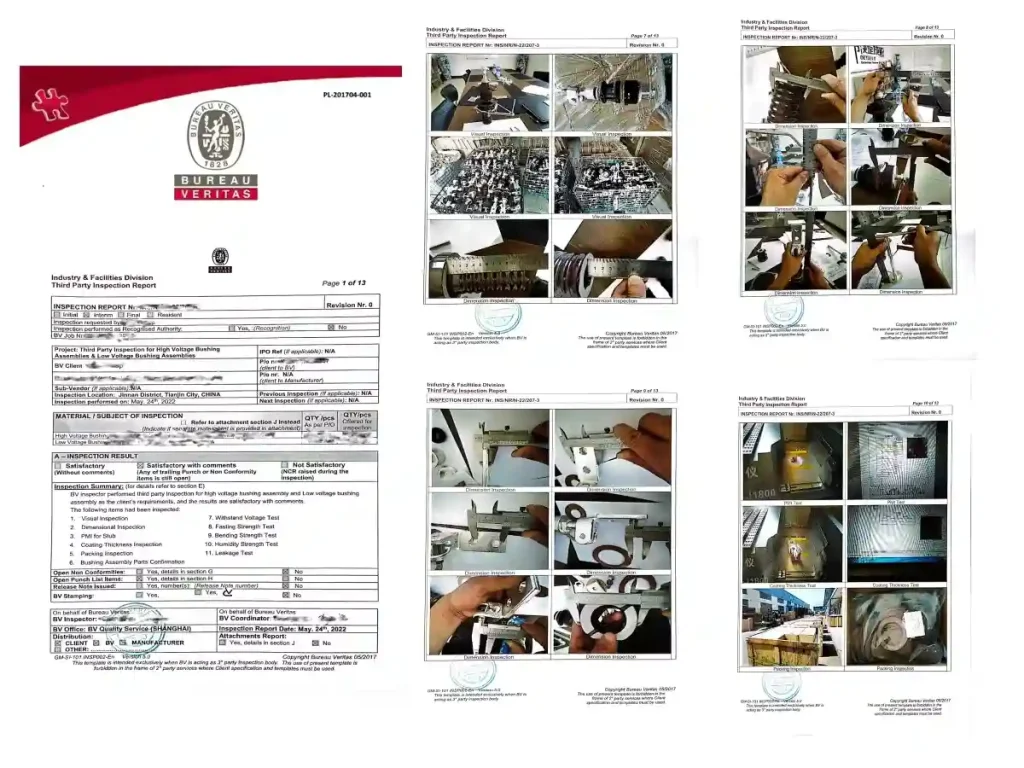
Third-party inspection: SGS, TÜV, Bureau Veritas, or Intertek available upon request.
Cooling & Overload Capability
| Cooling Mode | kVA Rating | Typical Application |
|---|---|---|
| AN (Air Natural) | 100% | Normal operation |
| AF (Air Forced – with fans) | 133% | Emergency overload or summer peak |
Class H insulation allows:
- 20% overload for 1 hour (emergency)
- 10% continuous overload at 40°C ambient
Procurement Guide for Data Center Applications
Step 1 – Select kVA Based on IT Load
| Total IT Load (kW) | UPS Rating (kVA) | Recommended Transformer (N config) | Recommended (N+1 config) |
|---|---|---|---|
| 600 – 800 kW | 800 – 1000 kVA | 1250 kVA | 2 × 1250 kVA |
| 800 – 1000 kW | 1000 – 1200 kVA | 1600 kVA | 2 × 1600 kVA |
| 1000 – 1500 kW | 1200 – 1800 kVA | 2000 kVA | 2 × 2000 kVA |
| 1500 – 2000 kW | 1800 – 2400 kVA | 2500 kVA | 2 × 2500 kVA |
| 2000 – 2500 kW | 2400 – 3000 kVA | 3150 kVA | 2 × 3150 kVA |
Step 2 – Choose K-Factor
If you do not have a harmonic study, provide:
- UPS type (6-pulse, 12-pulse, IGBT)
- Presence of active filters
- Percentage of non-linear load
We will recommend the optimal K-factor.
Step 3 – Specify Voltage and Tapping
- Primary voltage: Match utility or generator output (typical: 11kV, 10kV, 6kV)
- Secondary voltage: Match UPS input (typical: 480V, 415V, 400V)
- Tapping range: ±2×2.5% or ±5% on HV side (for voltage regulation)
Step 4 – Request Loss Capitalization Calculation
For data centers, transformer losses directly impact PUE. We provide a loss capitalization table based on:
- Local electricity cost ($/kWh)
- Transformer load factor (typical: 60-80% for N config, 40-60% for N+1)
- Cooling cost multiplier (1.2 – 1.5 due to room HVAC)
Typical Data Center Configurations
Configuration A: 2N (Fully Redundant)
- Two independent transformers, each sized for 100% of load
- Each transformer loaded at 40-50% in normal operation
- Select K-4 or K-7 (lower harmonics due to lower loading)
Configuration B: N+1 (Block Redundant)
- Three transformers, two active, one standby
- Active units loaded at 60-70%
- Select K-7 or K-13
Configuration C: N (No Redundancy)
- Single transformer feeding whole UPS chain
- Loaded at 70-85%
- Select K-13 or K-20
Our dry-type transformers are specifically optimized for hyperscale and edge data centers. Unlike standard industrial units, these are engineered with a high K-factor rating (up to K-13) to mitigate the thermal effects of non-linear loads and harmonics generated by switching power supplies.
[Asia Power] – Transformer Engineering Department
K-Factor Rated Dry-Type Transformers for Mission-Critical Data Centers
IEEE C57.110 • IEC 60076 • Class H Insulation • Factory Tested